Fault Seal Analysis: Critical for Hydrocarbon Exploration and Field Development
Understanding the Subsurface Barriers to Fluid Flow
In the complex world of hydrocarbon exploration and production, understanding fluid migration and entrapment is paramount. Faults, geological discontinuities where rocks have fractured and moved, play a dual role: they can act as conduits for fluid flow or, crucially, as barriers that trap hydrocarbons, forming economically viable reservoirs. Fault Seal Analysis is the specialized discipline dedicated to evaluating the sealing capacity of these faults, a critical factor in de-risking exploration prospects and optimizing field development strategies.
Misinterpreting fault seal can lead to significant financial losses, from drilling dry wells to inefficient production from compartmentalized reservoirs. Therefore, a robust Fault Seal Analysis is indispensable for accurate reserve estimation, well placement, and effective reservoir management.
Key Concepts in Fault Seal Analysis
Effective Fault Seal Analysis integrates structural geology, sedimentology, and petrophysics to predict whether a fault will retain hydrocarbons over geological time. Two primary mechanisms govern fault sealing:
1. Juxtaposition Seal
Juxtaposition seal occurs when impermeable lithologies (e.g., shales) are brought against permeable reservoir rocks across a fault plane. This forms a physical barrier to fluid migration. The analysis involves constructing Allan Maps or juxtaposition diagrams, which illustrate the lithological contacts along the fault plane. These diagrams are generated by projecting stratigraphy onto the fault surface, allowing geoscientists to identify areas where reservoir sands are juxtaposed against non-reservoir shales or other sealing units. Understanding these contacts is fundamental for predicting potential hydrocarbon traps and assessing compartmentalization within a field .
2. Fault Rock Seal (Membrane Seal)
Beyond simple juxtaposition, the fault zone itself can become a sealing barrier due to the presence of fault rocks. During fault movement, softer, ductile lithologies (primarily shales) can be smeared or dragged into the fault plane, forming a low-permeability fault gouge. This gouge acts as a membrane, preventing fluid flow across the fault. The most widely used quantitative method to predict the sealing capacity of fault gouge is the Shale Gouge Ratio (SGR). SGR is calculated as the sum of the thickness of shale beds that have passed through a given point on the fault plane, divided by the total fault throw. Higher SGR values generally indicate a greater proportion of shale in the fault zone, leading to a more effective seal .
The Integrated Approach to Fault Seal Analysis
Modern Fault Seal Analysis combines these concepts with advanced subsurface data and modeling techniques. The image below visually represents these critical components:
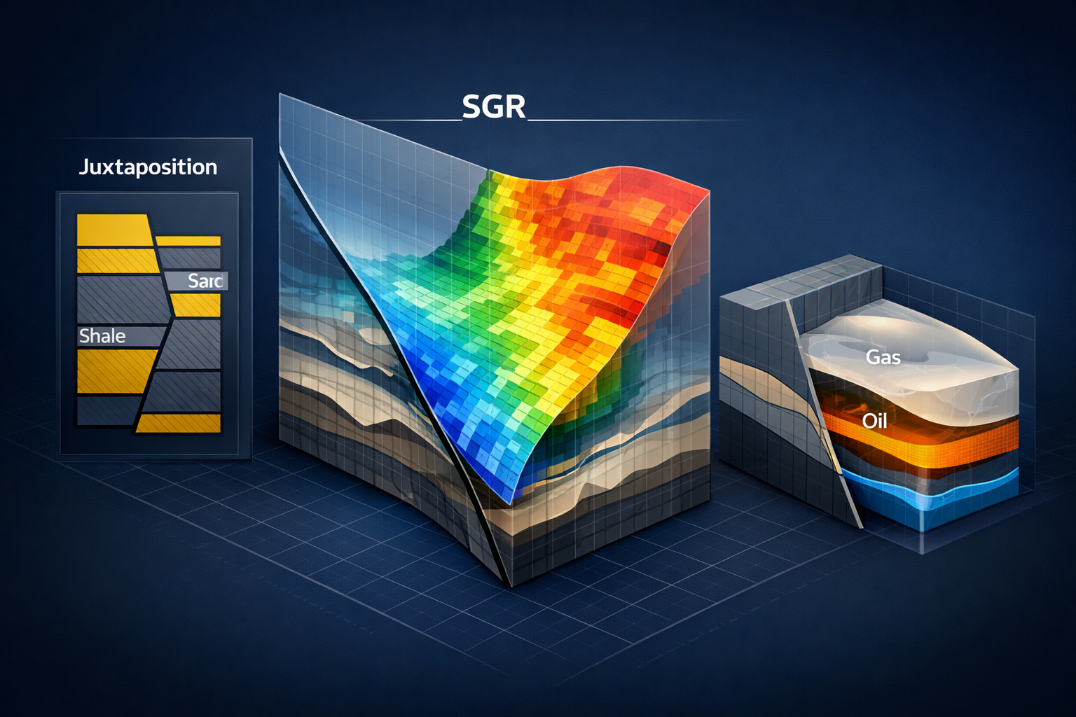
•Juxtaposition Diagram (Left Panel): Illustrates how different lithologies (sand and shale) are brought into contact across a fault, highlighting potential sealing or leaking scenarios.
•Shale Gouge Ratio (SGR) Map (Center Panel): A 3D representation of the fault plane, color-coded by SGR values. Areas with high SGR (red/orange) indicate strong sealing potential, while low SGR areas (blue/green) suggest potential leakage pathways.
•Hydrocarbon Entrapment (Right Panel): A conceptual model showing oil and gas trapped against a sealing fault, demonstrating the practical outcome of effective fault seal.
This integrated workflow typically involves:
1.Structural Interpretation: Detailed mapping of faults and horizons from seismic data.
2.Stratigraphic Framework: Establishing a robust stratigraphic model with accurate lithology distribution.
3.Petrophysical Characterization: Determining shale content and other rock properties from well logs.
4.Fault Property Modeling: Calculating SGR, clay smear potential, and other fault rock properties along the fault plane.
5.Fluid Flow Simulation: Incorporating fault properties into reservoir simulation models to predict fluid migration and compartmentalization.
Impact on Hydrocarbon Exploration and Field Development
Accurate Fault Seal Analysis provides immense value across the E&P lifecycle:
•Exploration: De-risks prospects by identifying viable traps and predicting hydrocarbon column heights. It helps prioritize drilling locations and reduces exploration uncertainty.
•Appraisal: Refines reservoir boundaries and identifies potential compartmentalization, guiding appraisal well placement.
•Development: Optimizes field development plans by predicting fluid flow barriers, informing well spacing, and designing effective waterfloods or EOR schemes. It is crucial for managing pressure regimes and preventing unwanted fluid breakthroughs.
•Carbon Capture and Storage (CCS): Increasingly, fault seal analysis is vital for assessing the long-term integrity of CO2 storage sites, ensuring that injected CO2 remains securely trapped underground .
The Future of Fault Seal Analysis
As subsurface data becomes more abundant and computational power increases, Fault Seal Analysis continues to evolve. Integration with machine learning, advanced geomechanics, and real-time monitoring promises even more sophisticated and predictive models. These advancements will further reduce exploration risk, enhance recovery from existing fields, and play a critical role in the energy transition by ensuring secure geological storage solutions.
References
[1] Allan, U.G. (1989). Model for hydrocarbon accumulation and entrapment against a sealing fault.
[2] Yielding, G., et al. (1997). Quantitative fault seal prediction.
[3] Ogilvie, S.R. (2020). Integrated Fault Seal Analysis: An Introduction.
Internal Links (Placeholders)
•Introduction to Structural Geology